QPainter coordinate system World->NDC->View transforms
-
Re: https://doc.qt.io/qt-5/coordsys.html
I'm trying to understand the transforms to map world coordinates to view coordinates. I'm using QGraphicsView in ui::widget, created a painter on a new QImage and added QGraphicsPixmapItem(QPixmap::fromImage(myImage)) to the QGraphicsScene. A filled rectangle for testing displays correctly in graphicsScene coordinates with the painter viewport equal to the image and graphicsview size.
I want to continue in world coordinates, but the documentation is somewhat abstruse regarding matrix transforms. I'm used to multiplying a 1x3 vector [x,y,1] by a 3x3 translation matrix [(1,0,Tx), (0,1,Ty), (0,0,1)] to map world coordinates to normalized device coordinates, a square with (0,0) at the lower right corner and (1,1) at the upper right, then NDC to device or view coordinates. Tying to make sense of world to window to view in qpainter. Documents show a logical point at a (0,0) center mapped to (50,50) window mapped to whatever the viewport is. How do I construct a transform to the Window coordinates? Can't seem to find out just what that Window QRect is. Window and viewport are the same with world to window xform an identity matrix? -
Re: https://doc.qt.io/qt-5/coordsys.html
I'm trying to understand the transforms to map world coordinates to view coordinates. I'm using QGraphicsView in ui::widget, created a painter on a new QImage and added QGraphicsPixmapItem(QPixmap::fromImage(myImage)) to the QGraphicsScene. A filled rectangle for testing displays correctly in graphicsScene coordinates with the painter viewport equal to the image and graphicsview size.
I want to continue in world coordinates, but the documentation is somewhat abstruse regarding matrix transforms. I'm used to multiplying a 1x3 vector [x,y,1] by a 3x3 translation matrix [(1,0,Tx), (0,1,Ty), (0,0,1)] to map world coordinates to normalized device coordinates, a square with (0,0) at the lower right corner and (1,1) at the upper right, then NDC to device or view coordinates. Tying to make sense of world to window to view in qpainter. Documents show a logical point at a (0,0) center mapped to (50,50) window mapped to whatever the viewport is. How do I construct a transform to the Window coordinates? Can't seem to find out just what that Window QRect is. Window and viewport are the same with world to window xform an identity matrix?I set the Viewport to the QImage, since that is the device being painted upon. Since the QPainter::window is supposed to be the same as world, I have no idea what the worldtransform does, if anything, since there doesn't appear to be a world qrectf to be found. I can setViewport and setWindow, but no setWorld, so what is a worldTransform? From what and to what does it transform? Logical coordinates are in a Window. Refer to the Analog Clock, hrm, that manipulates a Window, not a World, which is transformed to a RasterWindow. Color me Qt::Confused, but press on I must. Forget about world2ndc and ndc2view from analytical geometry, Qt wasn't designed to do calculus, just focus on window2view.
-
From my feeble understanding after reading Blanchette&Summerfield: The Viewport rectangle is the device upon which QPainter paints (pixmap, image), with (0,0) in the upper left corner, y increasing downward. Instead of using those device coordinates, you can use World coordinates, which QPainter calls "Window" logical coordinates. For a window rectangle with the origin(0,0) at the center, y increasing upward, upper left corner (-50,50), lower right corner (50,-50), create a rectangle with those two corners and painter.setWindow(that QRect). What happened to World? There is none. What QPainter calls "World" is a transformation matrix applied to Window, for example:
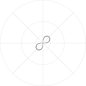
QMatrix matrix;
matrix.rotate(45.0);
painter.setWorldTransform(matrix);
// do stuff at a 45-degree tilt
I was able to use the Viewport-Window system to draw a lemniscate in polar coordinates (r, theta), but I used this function for World-Window:
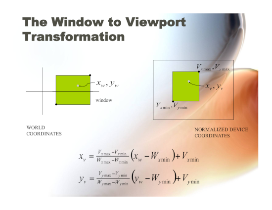
This is taken from Foley & van Dam Computer Graphics, Ch 5.5, fig. 5.15 -
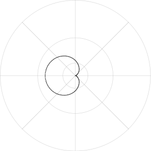
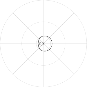
PolarGraph::PolarGraph()
{
    int imageWidth = 600, imageHeight = 600;
    image = new QImage(imageWidth, imageHeight, QImage::Format_RGB32);
    image->fill(Qt::white);
    painter = new QPainter(image);
    painter->setRenderHint(QPainter::Antialiasing);
    View.setSize(QSize(imageWidth, imageHeight));
    painter->setViewport(View);
    painter->setViewTransformEnabled(true);
    Window.setTopLeft(QPoint(-300, 300));
    Window.setBottomRight(QPoint(300,-300));
    painter->setWindow(Window);
    painter->setWorldMatrixEnabled(true);
    World.setTopLeft(QPointF(-10.,10.));
    World.setBottomRight(QPointF(10.,-10.));

    QPen myPen;
    myPen.setColor(Qt::lightGray);
    myPen.setWidth(1);
    painter->setPen(myPen);
    for (qreal i = 0; i < 360; i+=45) {
        painter->save();
        painter->rotate(i);
        painter->drawLine(QPoint(-300,0), QPoint(300,0));
        painter->restore();
    }
    QPoint center(0, 0);
    painter->drawEllipse(center,50,50);
    painter->drawEllipse(center,150,150);
    painter->drawEllipse(center,299,299);
    myPen.setColor(Qt::black);
    myPen.setWidth(2);
    painter->setPen(myPen);
    plotLemniscate();
    image->save("lemniscate.png");
    plotCardiod();
    image->save("cardiod.png");
    plotCurve1();
    image->save("curve1.png");
    plotCurve2();
    image->save("curve2.png");
}

void PolarGraph::plotCurve1()
{
    // r=2cos(Θ/3)
    qreal r;
    for (qreal theta = 0.; theta < M_PI*2; theta += 0.01) {
        r = qCos(theta/3.);
        plotRTheta(r, theta);
        plotRTheta(r, -theta);
    }
}

void PolarGraph::plotCurve2()
{
    // r=cos3Θ
    qreal r;
    for (qreal theta = 0.; theta < M_PI*2; theta += 0.01) {
        r = qCos(theta * 3.);
        plotRTheta(r, theta);
    }
}

void PolarGraph::plotLemniscate()
{
    // r^2 = sin(2Θ)
    // r = +-sqrt(sin(2Θ)
    qreal r;
    for (qreal theta = 0.; theta < M_PI*2; theta += 0.01) {
        r = qSqrt(qSin(theta * 2.));
        plotRTheta(r, theta);
        plotRTheta(-r, theta);
    }
}

void PolarGraph::plotCardiod()
{
    // r=1-cosΘ
    qreal r;
    for (qreal theta = 0.; theta < M_PI * 2.; theta += 0.01) {
        r = 1 - qCos(theta);
        plotRTheta(r, theta);
    }
}

void PolarGraph::plotRTheta(qreal R, qreal Theta)
{
    QPoint Pv;
    QPointF Pw;
    Pw = QPointF(R, 0.);
    qreal thetaDegrees = qRadiansToDegrees(Theta);
    int x;
    Pv = World2View(Pw);
    x = Pv.x();
    painter->save();
    painter->rotate(thetaDegrees);
    painter->drawPoint(x,0);
    painter->restore();
}

QPoint PolarGraph::World2View(QPointF Pworld)
{
    // Transform matrix from Foley & van Dam _Computer Graphics_ Ch 5.5, fig 5.15
    /* View-ViewMin       World-WorldMin
     * --------------- =  -------------------
     * ViewMax-ViewMin    WorldMax-WorldMin
     *
     *     Vmax-Vmin
     * V = ---------(W-Wmin)+Vmin = S(W-Wmin)+Vmin
     *     Wmax-Wmin
     */
    QPoint Pview;
    QPointF PviewF;
    Vmax = Window.topRight();
    Vmin = Window.bottomLeft();
    QPointF WtopLeft = QPointF(-5., 5.);
    QPointF WbottomRight = QPointF(5., -5);
    World = QRectF(WtopLeft, WbottomRight);
    Wmax = QPointF(World.topRight());
    Wmin = QPointF(World.bottomLeft());

    Sx = ( Vmax.x() - Vmin.x() ) / ( Wmax.x() - Wmin.x() );
    Sy = ( Vmax.y() - Vmin.y() ) / ( Wmax.y() - Wmin.y() );

    PviewF.setX(Sx * (Pworld.x() - Wmin.x()) + Vmin.x());
    PviewF.setY(Sy * (Pworld.y() - Wmin.y()) + Vmin.y());
    Pview = PviewF.toPoint();
    return Pview;
}